
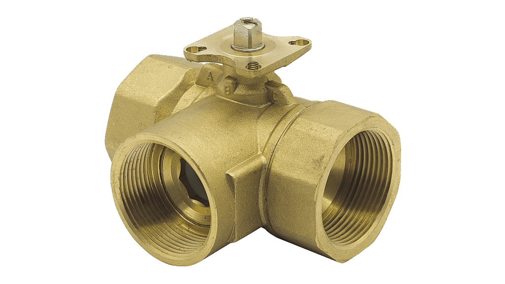
Connection diameter alone does not determine the control quality of a three-way valve. Design flow, available differential pressure, port arrangement and actuator characteristics must be considered together. In underfloor-heating and central-heating mixing assemblies, oversizing can impair controllability, while undersizing restricts flow.
This worked calculation complements the general three-way valve selection guide (Turkish). It compares alternative Kvs values and mixing-temperature targets at a design flow of 2.4 m³/h.
Calculation table 1: Three Kvs values at the same flow
For preliminary water sizing, Δp = (Q/Kvs)². The table assumes the same port path, a fully open valve and constant Q = 2.4 m³/h; it does not model a change in the pump operating point.
| Kvs (m³/h) | Δp (bar) | Δp (kPa) |
|---|---|---|
| 6.3 | 0.1451 | 14.51 |
| 10 | 0.0576 | 5.76 |
| 16 | 0.0225 | 2.25 |
The smallest pressure drop does not automatically identify the best control valve. Increasing Kvs changes the valve’s share of the available differential pressure; evaluate low-load controllability and the actual port characteristic as well.
Calculation table 2: Branch flows at different mixing targets
Assume a constant 60 °C hot supply, 30 °C return and total mixing flow of 2.4 m³/h, with negligible mixing heat loss and similar fluid density and specific heat.
| Target (°C) | Hot branch (m³/h) | Return branch (m³/h) |
|---|---|---|
| 35 | 0.4 | 2.0 |
| 40 | 0.8 | 1.6 |
| 45 | 1.2 | 1.2 |
These flows are not actuator-opening percentages. Record target and measured temperatures, total flow and the differential pressure across the valve during commissioning.
What Kvs means—and what it does not mean
Kvs is the rated flow coefficient of the fully open valve, conventionally expressed as the water flow in m³/h at approximately 1 bar differential pressure. For water, the practical first-pass relation is Q = Kv × √(Δp in bar), or Kv = Q / √Δp. This is a simplified sizing relation; glycol content, viscosity, cavitation and the manufacturer’s flow characteristic may require a more detailed assessment.
Kvs is not the nominal pipe diameter DN, nor does it imply a linear relationship between actuator rotation and flow. Mixing and diverting port paths can have different characteristics. Obtain the actual port diagram for the selected valve.
Worked example: 2.4 m³/h at 16 kPa
Assume a design flow of 2.4 m³/h and a permissible fully open valve pressure drop of 16 kPa, or 0.16 bar. Required Kv = 2.4/√0.16 = 6.0 m³/h. The published ATLAS brass three-way valve table gives Kvs = 6.3 for DN20 and Kvs = 10 for DN25. At Kvs = 6.3, the estimated fully open drop at 2.4 m³/h is (2.4/6.3)² = 0.145 bar, approximately 14.5 kPa.
This calculation does not automatically approve DN20 for the project. Confirm the relevant flow path, authority, connection, working pressure, minimum controllable flow, shut-off requirements and the specific valve/actuator combination.
Mixing 60 °C supply and 30 °C return into 40 °C
If heat loss during mixing is negligible and the streams have similar density and specific heat, Tmix ≈ (Qhot × Thot + Qreturn × Treturn)/(Qhot + Qreturn). For Thot = 60 °C, Treturn = 30 °C and Tmix = 40 °C, the hot-water fraction is (40−30)/(60−30) = 1/3. With 2.4 m³/h total flow, the hot branch would carry about 0.8 m³/h and the return branch 1.6 m³/h.
A one-third hot-water fraction does not equal a 33% actuator command. Port characteristics and unequal pressure drops make stroke-to-flow behavior nonlinear. Use a measured mixed-temperature signal and an appropriate feedback controller.
Valve authority and port direction
Valve authority describes how the control valve’s open-position pressure drop relates to the changing pressure conditions of its circuit. Higher authority generally improves predictability of control; the appropriate reference pressure depends on the hydraulic arrangement. A three-way mixing circuit must not automatically be evaluated with the same simplified rule used for every two-way valve.
Identify A, B and AB—or the manufacturer’s equivalent port symbols—on the installation drawing before connection. Not all three-way valves are suitable for both mixing and diverting duties; confirm the supported function for the exact variant.
Seven acceptance checks
Document design flow and allowed valve pressure drop. Confirm Kvs for the intended port path. Verify DN, pressure class, temperature range and fluid compatibility. Match the physical ports to the schematic. Check actuator travel and control signal direction. Measure mixed-water temperature at both low and high load. Include filtration, air removal, pressure behavior and service access in commissioning records.
Applying the method to ATLAS valves
ATLAS publishes Kvs data for DN20–DN40 brass valves and offers larger cast-valve variants. Final selection must be based on the current drawing, port-flow diagram and validated valve–actuator set, not on DN alone. This helps avoid excessive capacity and unstable temperature control.
Share design flow, supply/return temperatures, the hydraulic schematic and the target pressure drop for a model-specific ATLAS three-way valve selection.
The calculations are illustrative; port characteristics and operating limits must be verified for each product.