ATLAS • IoT
IoT Electromagnetic Flow Meter – Remote Monitoring & Data Management
ATLAS combines its metering-system production and industrial automation expertise with electromagnetic flow measurement, GSM/4G communication options and the AtlasServer.io monitoring platform. Compatible external RTU/modem hardware is selected according to the project.
AtlasServer.io — The 24-month free platform entitlement applies to eligible IoT flow meter packages. Device/user limits, activation and renewal terms are specified in the quotation. SIM cards, cellular data plans, installation and third-party fees are excluded unless expressly included. Cellular or LoRaWAN connectivity is not assumed to be built into every meter.
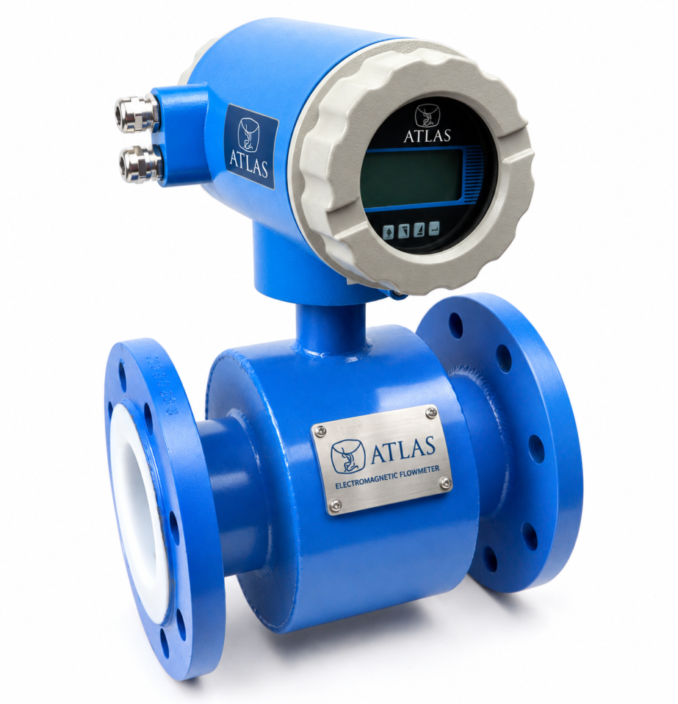
Electromagnetic Flow Meter
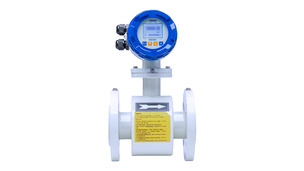
The electromagnetic flow meter is used to measure the volumetric flow rate of conductive liquids in full pipes. The flanged construction allows the sensor to be connected directly to the pipeline. The design has no moving measuring part; it is intended for water, wastewater, irrigation and, with appropriate material selection, industrial process applications.
Atlas is the point of contact for application-appropriate product selection and supply. At ordering, the fluid, flow rate, pressure, temperature and communication requirement are evaluated together.
- Compact series DN15–DN2000; wide series up to DN2800 with project-specific options.
- Forward and reverse flow measurement; instantaneous flow rate and total volume display.
- Compact or separate-type transmitter selection.
- 4–20 mA, pulse and RS485/Modbus; optional HART depending on configuration.
- The electrodes and inner lining are selected according to the chemical and corrosive properties of the fluid.
DN15–DN2800 Diameter and Flow Rate Pre-Selection Table
The following flow rates This is an Atlas engineering calculation; it is not the manufacturer’s calibration range or guaranteed minimum/maximum flow rate. The relation Q = π × (D/1000)² × v × 900 has been used. The nominal DN value is taken for D; the actual inner diameter and lining thickness may change the results. The 1, 3 and 5 m/s columns are for diameter comparison only.
| Nominal diameter | 1 m/s — m³/h | 3 m/s — m³/h | 5 m/s — m³/h | Selection range |
|---|---|---|---|---|
| DN15 | 0,64 | 1,91 | 3,18 | Compact series range; depending on model selection |
| DN20 | 1,13 | 3,39 | 5,65 | Compact series range; depending on model selection |
| DN25 | 1,77 | 5,3 | 8,84 | Compact series range; depending on model selection |
| DN32 | 2,9 | 8,69 | 14,48 | Compact series range; depending on model selection |
| DN40 | 4,52 | 13,57 | 22,62 | Compact series range; depending on model selection |
| DN50 | 7,07 | 21,21 | 35,34 | Compact series range; depending on model selection |
| DN65 | 11,95 | 35,84 | 59,73 | Compact series range; depending on model selection |
| DN80 | 18,1 | 54,29 | 90,48 | Compact series range; depending on model selection |
| DN100 | 28,27 | 84,82 | 141,37 | Compact series range; depending on model selection |
| DN125 | 44,18 | 132,54 | 220,89 | Compact series range; depending on model selection |
| DN150 | 63,62 | 190,85 | 318,09 | Compact series range; depending on model selection |
| DN200 | 113,1 | 339,29 | 565,49 | Compact series range; depending on model selection |
| DN250 | 176,71 | 530,14 | 883,57 | Compact series range; depending on model selection |
| DN300 | 254,47 | 763,41 | 1.272,35 | Compact series range; depending on model selection |
| DN350 | 346,36 | 1.039,08 | 1.731,8 | Compact series range; depending on model selection |
| DN400 | 452,39 | 1.357,17 | 2.261,95 | Compact series range; depending on model selection |
| DN450 | 572,56 | 1.717,67 | 2.862,78 | Compact series range; depending on model selection |
| DN500 | 706,86 | 2.120,58 | 3.534,29 | Compact series range; depending on model selection |
| DN600 | 1.017,88 | 3.053,63 | 5.089,38 | Compact series range; depending on model selection |
| DN700 | 1.385,44 | 4.156,33 | 6.927,21 | Compact series range; depending on model selection |
| DN800 | 1.809,56 | 5.428,67 | 9.047,79 | Compact series range; depending on model selection |
| DN900 | 2.290,22 | 6.870,66 | 11.451,11 | Compact series range; depending on model selection |
| DN1000 | 2.827,43 | 8.482,3 | 14.137,17 | Compact series range; depending on model selection |
| DN1200 | 4.071,5 | 12.214,51 | 20.357,52 | Compact series range; depending on model selection |
| DN1400 | 5.541,77 | 16.625,31 | 27.708,85 | Compact series range; depending on model selection |
| DN1600 | 7.238,23 | 21.714,69 | 36.191,15 | Compact series range; depending on model selection |
| DN1800 | 9.160,88 | 27.482,65 | 45.804,42 | Compact series range; depending on model selection |
| DN2000 | 11.309,73 | 33.929,2 | 56.548,67 | Compact series range; depending on model selection |
| DN2200 | 13.684,78 | 41.054,33 | 68.423,89 | Wide series / project-specific confirmation |
| DN2400 | 16.286,02 | 48.858,05 | 81.430,08 | Wide series / project-specific confirmation |
| DN2600 | 19.113,45 | 57.340,35 | 95.567,25 | Wide series / project-specific confirmation |
| DN2800 | 22.167,08 | 66.501,23 | 110.835,39 | Wide series / project-specific confirmation |
Diameter range: The compact series DN15–DN2000 and the extended series options cover the DN6–DN2800 range. The list here starts from DN15; intermediate diameters, especially sizes above DN2000, are not a stock or firm production commitment. DN, PN, flange standard, lay length and lining combination are verified at the quotation stage.
Technical Options
| Measurement principle | Faraday electromagnetic induction principle; conductive liquids and suitable slurry applications. |
|---|---|
| Accuracy options | ±%0,5 / ±%0,25; depending on the selected model and operating conditions. |
| Conductivity | >5 µS/cm required for product selection; application confirmation required for low-conductivity liquids. |
| Pressure options | In the extended series listing: 6, 10, 16, 25, 40 and 64 bar. Not every pressure is considered available in every diameter. |
| Velocity range | Extended series listing: 0,05–12 m/s; 0,1–15 m/s upon request. The final range depends on the selected transmitter and sensor. |
| Power supply | Compact version: 85–265 VAC or 24 VDC. Extended series: 85–265 VAC / 18–38 VDC options. |
| Protection | Compact version IP65; IP67 / IP68 in other variants. Sensor and transmitter protections must be verified separately. |
| Electrode | 316L, Hastelloy B/C, titanium, tantalum, platinum and tungsten carbide options. |
| Inner lining | PTFE, neoprene/rubber; PU, FEP and PFA depending on the variant. Not all materials are offered in all diameters. |
| Temperature | Depends on the lining and liner. According to the general technical data, neoprene 0…70 °C, FEP −20…180 °C, PTFE −40…180 °C; the datasheet of the model to be purchased shall be taken as the basis. |
Automation and Remote Flow Reading
The 4–20 mA output can be used for transmitting instantaneous flow to a PLC/DCS system, and the pulse output for volume counting. Measurement can be transferred to a compatible SCADA or data acquisition system via the RS485/Modbus connection. HART and Modbus selection must be specified at ordering; simultaneous use is subject to hardware verification.
LoRaWAN, GSM/4G or NB-IoT a suitable external RTU or communication gateway is required for remote reading via. These are not standard built-in features of the flow meter specified here. In integration, the register map, pulse coefficient, power supply and communication compatibility are checked. The flow meter performs the measurement; if valve control is required, separate control equipment is selected.
Application and Installation Selection
- The sensor measurement section must be kept completely filled with liquid throughout operation.
- The fluid conductivity and the compatibility of electrode and lining are evaluated together.
- Grounding, equipotential bonding and cabling are carried out according to the manual of the selected model.
- Inlet/outlet straight pipe lengths are determined by the manufacturer’s installation drawing according to the placement of elbows, pumps and valves.
- For gases, steam and liquids without sufficient conductivity, a different measurement technology should be evaluated.
Quotation and Technical Documents
For a quotation, please share the DN, minimum/normal/maximum flow rate, fluid and its conductivity, temperature, operating pressure, flange standard, power supply, IP requirement and output protocol. The technical datasheet, dimension drawing, wiring diagram and calibration certificate must be matched to the selected order code. CE/MID or explosive atmosphere compliance is assessed only with the valid documentation belonging to the relevant model.
Request a quote for an electromagnetic flow meter · Explore remote reading and automation products