
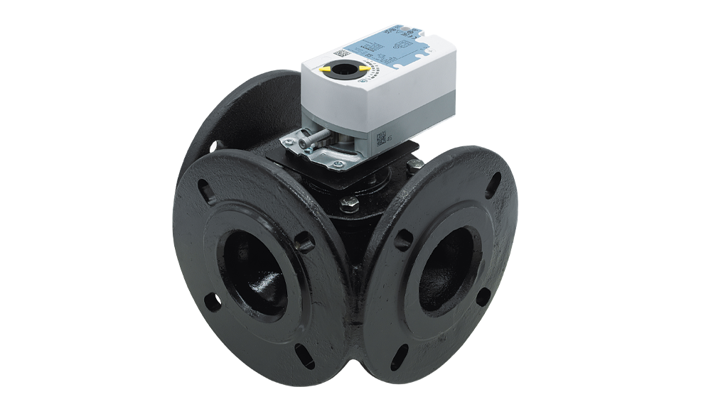
Correct valve sizing does not ensure correct automation. A mismatch of supply voltage, command signal, torque, stroke or power-loss behaviour can create unstable mixing or move a three-way valve toward the wrong port. This engineering guide addresses the actuator interface and mechanical pairing rather than repeating Kvs sizing.
1. Supply voltage is not the control signal
A 230 V actuator description identifies its supply, not whether it accepts On/Off, floating 3-point or analogue modulation. Different 24 VAC, 24 VDC and 230 VAC variants require different controller outputs and protections. The same valve body may accept actuators with different command interfaces.
The ATLAS three-way brass valve page lists AC 220 V, 50/60 Hz and 6 N·m for a motor variant. Its general “proportional control” statement must not be taken as proof that every variant has a 0–10 V input; check the exact actuator wiring diagram.
2. On/Off, 3-point floating and 0–10 V
On/Off drives a valve between defined end positions. A floating three-point actuator typically responds to open, stop and close commands; effective position may depend on running time or feedback. A modulating 0–10 V input specifies a continuous position demand, while other models may use 2–10 V or 4–20 mA.
With an illustrative linear 0–10 V to 0–90° mapping, 6 V commands 54°: θ = 90 × U/10. Real travel limits, control direction and valve port geometry may differ. A 60% command is not necessarily 60% of hydraulic flow.
3. Match torque against actual duty, not DN alone
The required torque is affected by maximum differential pressure, seating design, temperature, startup friction and shaft coupling. Compare the actuator’s available torque with the specific valve manufacturer’s required-torque data at the intended conditions.
For a purely hypothetical duty of 4 N·m and a chosen design multiplier of 1.5, an initial target would be 6 N·m. Neither the multiplier nor the result is a universal approval of a particular ATLAS combination.
4. Stroke, travel time and feedback
Many rotary three-way valves use a 90° nominal stroke, but stop points and usable travel depend on the selected arrangement. A hypothetical 90° movement completed in 60 seconds corresponds to 1.5°/s. Excessively rapid action can aggravate hydraulic transients; slow action can introduce control lag.
The command signal is not the same as verified position. Auxiliary limit switches or analogue position feedback, if fitted, improve commissioning and fault diagnosis. Confirm them in the exact actuator option code.
5. Define the safe state on power loss
An actuator may stay in place when de-energised, use spring return, or move using stored energy. These are materially different behaviours. “Electric actuator” alone does not imply spring-return protection. Define the safe port position for the specific mixing or diverting circuit.
Freeze risk in a heat-pump loop, overheating in a boiler circuit and a stopped circulation pump lead to different fail-action requirements. Validate the safety function across sensor, controller, power and hydraulics rather than relying on the motor label.
6. Commissioning checklist
Confirm the manufacturer-specific A/B/AB port arrangement, measure supply and command outputs, verify mechanical travel and movement direction, test position indication, then log supply/return temperatures at partial and full loads.
Include manual override, automatic demand, de-energisation and restart tests. For ATLAS selection provide DN/Kvs, design flow, maximum operating Δp, actuator torque, voltage, command type and required fail position.
Evaluate ATLAS three-way brass valves and compatible actuator variants using your hydraulic schematic and controller specification. 3-Way Brass Valves · Actuated Valves.
Worked figures are illustrative; exact valve–actuator compatibility and safety behaviour require model-specific approval.
Related solution and technical reference
Smart Building and HVAC Solutions · Danfoss actuator control options