
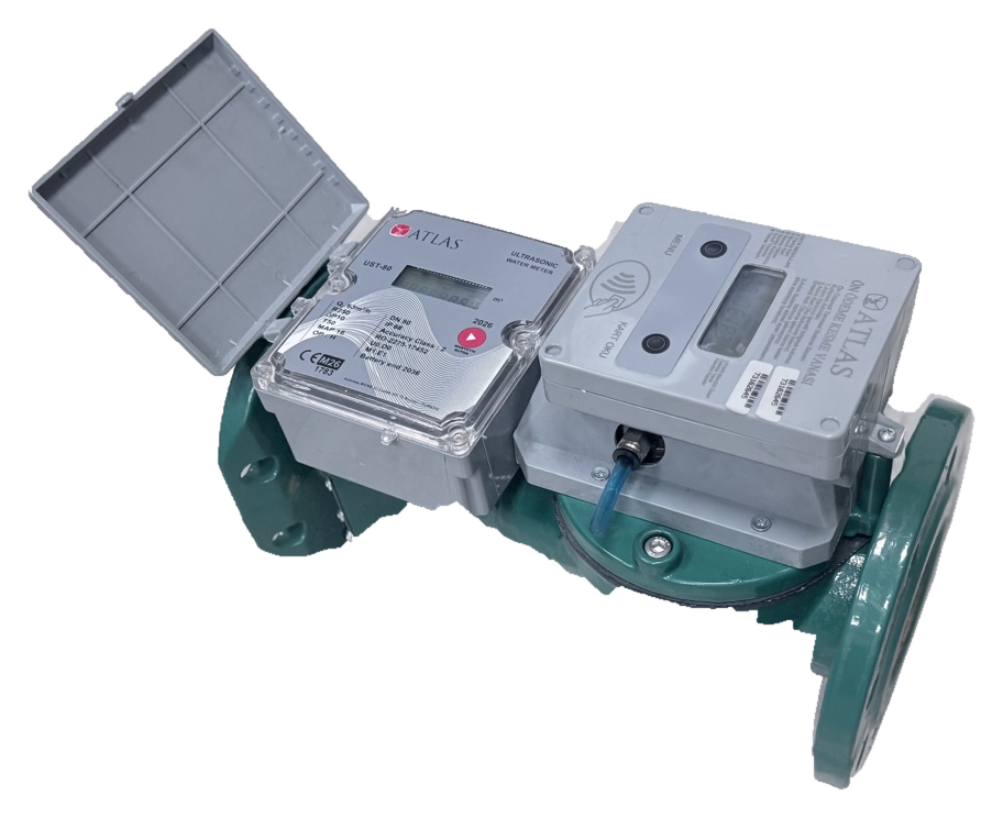
Choosing an irrigation meter by nominal pipe size alone often ignores the real reasons behind inconsistent field readings. A project must combine low-to-peak flow, full-pipe conditions, air management, sediment exposure and the integrity of remotely collected total-volume data. The following method is designed for engineering, procurement and acceptance teams working on ATLAS UTM meter and irrigation-hydrant projects.
Conceptual metering and telemetry functions, not a construction piping diagram. Scroll horizontally on narrow screens.
Start with the operating flow envelope
Record minimum, normal and maximum measured or predicted flow for each station, including the number of simultaneous open hydrants, pump cycling and pressure variation. Compare this profile against the selected meter model’s Q1, Q2, Q3 and Q4, not simply DN. Q3 denotes permanent flow, whereas Q4 is an overload condition for limited use, not a preferred continuous operating point.
The currently displayed ATLAS product table lists UTM80 Q1 = 0.25 m³/h and Q3 = 63 m³/h, and UTM100 Q1 = 0.25 m³/h and Q3 = 100 m³/h. Confirm the purchased hardware revision and legal metrology documentation before declaring conformity.
Manage full pipes and air pockets
Closed-conduit measurement relies on specified hydraulic conditions. High-point air pockets, partial emptying after pump shutdown and large volumes of air during first filling can undermine the measurement environment. A meter without a moving impeller is not automatically immune to bubbles, sediment or severely disturbed flow profiles.
Design the measuring point with adequate positive pressure, the manufacturer’s required straight-run sections and a project-specific air-release arrangement. Air/vacuum valves at high points and the actual meter installation must be considered together without introducing uncontrolled water-hammer risks.
Sediment and debris affect selection
Canal-fed, borehole and storage-tank schemes may carry sand, plant matter or mineral deposits. If a strainer or pre-filter is required, specify its mesh, clean-pressure drop and maintenance interval; do not put it directly against the meter unless the installation instructions permit it. Changed strainers, elbows or reducers can alter upstream flow profiles.
The US Bureau of Reclamation’s Water Measurement Manual discusses how sediment and floating material can compromise several measurement devices. The practical answer is not an absolute claim that one sensor technology can never be affected, but a documented water-quality and maintenance plan.
Treat the hydrant and telemetry as one system
A hydrant may contain distinct modules for metering, pressure monitoring and valve/access control. The integration schedule should map device ID, station ID, cumulative-volume units, timestamps, report interval and recovery after a communication outage. A cloud screen must distinguish “last received” from a genuinely current measurement.
ATLAS meter, hydrant and smart-irrigation offerings provide a project context; the exact RF, LoRaWAN, card or valve features depend on the selected and documented configuration. Do not assume every UTM device includes every remote-control option.
A transparent consumption example
Suppose a station operates at 35 m³/h for six hours. The idealised volume is 35 × 6 = 210 m³ per day, or 2,940 m³ over 14 identical days. Compare this planning number with the difference between local totaliser readings rather than presenting it as a guaranteed observed quantity. Actual pressure, emitter demand and pump operation cause flow to vary.
Remote reporting should reconcile start/end cumulative totals and report missing intervals, meter resets and time differences separately. Adding sparse instantaneous-flow samples is not automatically equivalent to a legally relevant metered volume.
Ten-point site acceptance plan
Run low, normal and high flow tests; inspect pump start/stop transients, air-release equipment, strainer condition, leaks, pressure losses, meter totaliser and remote volume agreement. Use a traceable reference where contractually required.
The SAT record should show meter model and serial number, DN, Q3, certificate revision, installation photographs, upstream/downstream distances, water-quality observations, data timestamps, communication-recovery tests and a signed deviation list. Unmatched model/certificate identities remain open technical issues.
Field acceptance checklist
- Document Qmin/Qtyp/Qmax and pump duty cycle.
- Verify filled-pipe, air-release and reverse-flow conditions.
- Record sediment protection and installation distances.
- Compare local cumulative volume and remote records.
- Match serial number, model revision and compliance papers.
Technical questions
Is DN sufficient to choose an irrigation meter?
No. Flow envelope, fluid quality, installation, head loss and model-specific approvals must be considered together.
Does a lost radio connection prove that consumption data are lost?
No. Test the meter’s local totaliser behaviour and any gateway/server buffering separately.
Scope and verification note: Q1/Q3 and stated R ratios on the current UTM webpage require model- and certificate-level reconciliation; this guide does not turn them into an unverified guarantee.