
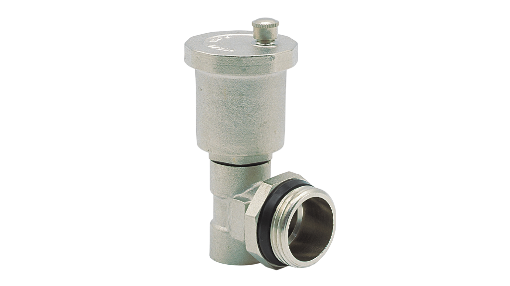
A noisy manifold, unstable flow indicator or slow-to-warm room is not necessarily a pump-control problem. Trapped air, circulating microbubbles and insufficient filling require different remedies. This field guide explains how automatic air vents and manifold fill/drain connections contribute to repeatable commissioning without turning model-specific limits into universal rules.
Conceptual loop-by-loop flushing sequence; follow the equipment installation drawing. Scroll horizontally on narrow screens.
Distinguish air locks from cavitation
Free air pockets can gather at high points and block flow. Dispersed microbubbles may circulate before reaching a suitable separation device. Pump cavitation is different: it may indicate inadequate inlet pressure or an NPSH problem and will not be solved merely by fitting an extra vent. Diagnose the hydraulic cause before replacing parts.
A small vent on a hydronic manifold is also not interchangeable with a large air/vacuum valve used on transmission water mains. Discharge capacity, maximum temperature and pressure, leakage requirements and installation geometry all matter.
Automatic vent versus fill/drain connection
An automatic vent releases accumulated gas under the conditions for which it was designed. A manifold fill/drain assembly provides access for positively flushing long loops during initial fill or service. Relying on a small float vent alone can leave a large air lock in a long radiant circuit.
The ATLAS air-vent product page identifies manifold ends and appropriate air-release points as potential locations. The exact connection size, orientation, isolation arrangement and service procedure must be checked for the selected part number.
Place the components where air can collect
Review actual high points, changes in pipe slope, near-boiler connections and manifold areas where velocity changes. A microbubble separator and a local float vent do not necessarily share the same optimum position. In heating systems, high temperature and lower absolute pressure can favour the release of dissolved gases, which informs air-separator placement.
Allow access for inspection, safe isolation and discharge away from live electrical parts. The published limits of a reference manufacturer must not be presented as ATLAS equipment ratings.
Flush the loops one by one
Make the boiler, pump and controllers safe. Confirm that temperature and pressure permit work; apply suitable backflow prevention and water-treatment instructions. Connect filling and drain hoses to the designed service points, closing all but one manifold circuit. Flush that circuit at a controlled rate until the returning water stream is continuous and visibly free of bulk air; then close it and open the next loop.
Once all circuits are purged, bring the system to its engineered cold pressure, inspect joints for leakage, then start the circulation pump according to the manufacturer’s procedure. Balance the loops and test zone controls afterwards; repeat pressure checks after the initial heating cycles.
Cold filling pressure is not universally 1.5 bar
The static difference between a low-level pressure gauge and the highest water-filled point is approximately Δp = ρgH/100,000 in bar. For a 12 m elevation difference, water imposes about 1.18 bar. If an illustrative 0.30 bar positive gauge margin is required at the top, the bottom gauge would need about 1.48 bar, before considering actual vessel pre-charge and equipment constraints.
This is a worked example, not a blanket filling-pressure instruction or a rating for any ATLAS air vent. The expansion vessel, relief settings, temperature and system height determine the design.
Troubleshooting and acceptance evidence
Persistent water discharge at a vent warrants inspection of contamination, float seating and the service connection. Repeated air ingress may indicate suction at low-pressure points, leaks or excessive fresh make-up water. Pump noise alone does not identify an air lock; clogged strainers and cavitation should be ruled out.
A handover record should cover manifold and circuit identifiers, filling direction, treatment water, initial/final cold pressure, confirmed purge for each loop, vent orientation, leak test, final flow readings and follow-up actions after thermal cycling.
Field acceptance checklist
- Make equipment safe; verify temperature and pressure.
- Purge one loop at a time to a continuous return stream.
- Check vent orientation, location and isolation.
- Calculate hydrostatic head with expansion-vessel design.
- Record leaks, noises and pressure after cycling.
Technical questions
Will a float vent automatically purge every loop during filling?
Not reliably. Long circuits typically need dedicated flushing via properly designed fill and drain points.
Is a cold pressure of 1.5 bar correct for every building?
No. Elevation, vessel pre-charge, system layout and safety-component limits determine the required pressure.
Scope and verification note: Purging and pressurisation must be carried out by qualified personnel following equipment instructions and local safety rules.