
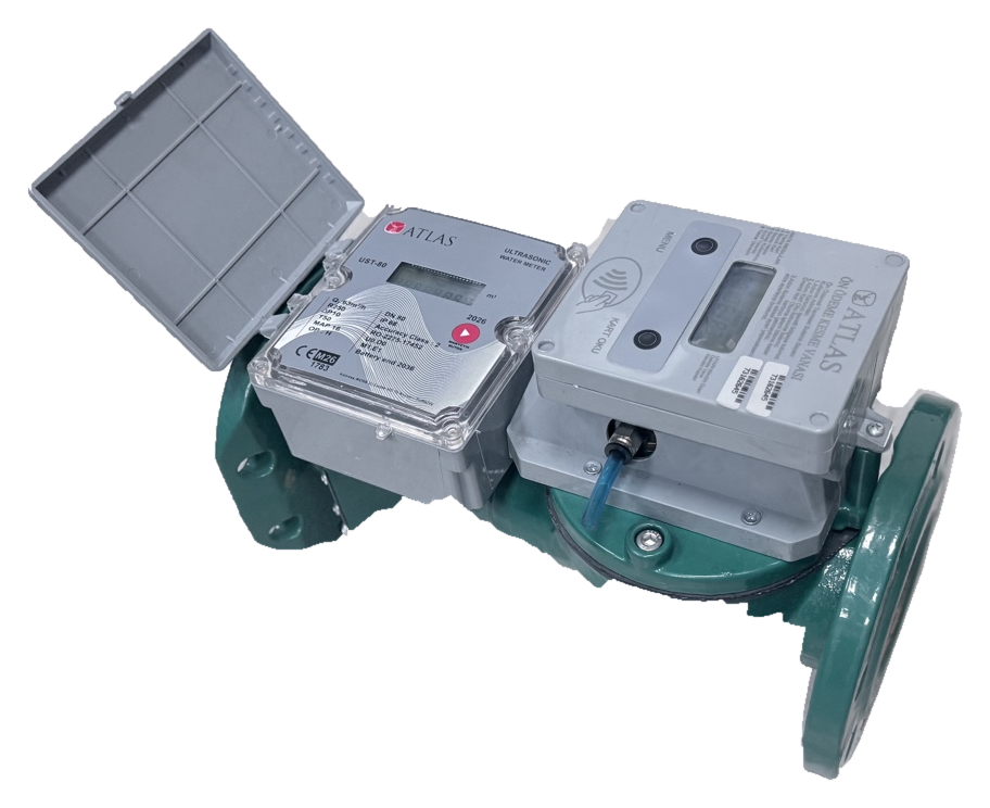
Original ATLAS agricultural irrigation meter photograph; the pictured device is not a soil-moisture sensor.
Engineering guide · Numerical examples are hypothetical, not product test results.
A soil-moisture reading of 22% is not, by itself, an irrigation command. The control system must know whether the sensor measures volumetric water content (VWC) or soil-water tension, and must relate that observation to root depth, soil texture and permissible depletion. The purpose of this guide is to turn a field measurement into a defensible irrigation trigger and application-volume calculation using the FAO-56 root-zone water-balance concept.
What volumetric water content actually means
VWC, normally denoted θ, is the volume of water divided by the bulk volume of soil. A reading θ=0.25 means 25% by volume, not that the soil is “25% full” in a universal sense. Field capacity θFC describes water retained after free drainage; permanent wilting point θWP describes water no longer effectively available to the plant. Texture, compaction and stratification alter both values. Dielectric sensors can respond to salinity, temperature, bulk density and poor soil contact, so field verification is essential.
FAO-56 root-zone storage: TAW and RAW
The total available water depth in a reasonably uniform root zone is TAW = 1000 × (θFC − θWP) × Zr, with effective root depth Zr in metres and TAW in millimetres. Readily available water is RAW = p × TAW, where p is the fraction that can be depleted before material water stress begins. The familiar p=0.50 is an example, not a universal plant constant. If the root zone has different soil layers, calculate storage in each layer and sum the results.
Worked example for a 2,000 m² zone
Assume an illustrative field with θFC=0.30, θWP=0.15, Zr=0.40 m and p=0.50. Then TAW = 1000 × 0.15 × 0.40 = 60 mm and RAW = 30 mm. Suppose actual depletion has reached 30 mm and the operational objective is to restore field capacity. The required net water is 2,000 m² × 0.030 m = 60 m³. At a hypothetical application efficiency of 85%, the gross delivered volume is 60/0.85 = 70.6 m³. If measured zone flow is 8 m³/h, idealized delivery time is 70.6/8 ≈ 8.82 h. In practice, infiltration, system capacity and zone sequencing must govern the delivery schedule.
Locating and validating sensors in the root zone
A single probe does not represent a whole field or the entire root profile. Divide the landscape into management zones with comparable soil, crop and exposure. For suitable crops, readings at more than one depth can show whether water has reached lower roots or is draining beyond them. A probe next to an emitter and another between crop rows will see different wetting patterns. Minimize air gaps around probes, protect wiring and log sensor depth. Compare selected sensor readings with sampled soil or a trusted field method before fixing automated thresholds.
Daily depletion and the role of evapotranspiration
A simplified water-balance update is Dr,new = Dr,old + ETc − Pe − I_net, where Pe is effective rainfall and I_net is irrigation actually retained in the root zone. Add runoff, deep percolation or capillary rise where they are significant. If starting depletion is 18 mm, crop ETc is 5 mm/day and effective rain is 1 mm, the new depletion without irrigation is 22 mm. With RAW=30 mm, the nominal trigger has not yet been reached. Forecast heat, irrigation shifts and uncertainty in the measurements still affect operational timing.
Control logic that survives noisy and missing data
Opening a solenoid from one instantaneous reading may cause hunting. Define data-quality flags, filtering, different start/stop thresholds, minimum valve dwell times and a maximum watering duration. The loss of a sensor, radio link or controller clock requires a documented fallback strategy: local schedule, operator confirmation or controlled shutdown depending on the site. Forecast precipitation should not be stored as measured rainfall. Use a water meter to confirm delivered volume and retain separate timestamps for the command, actual execution and feedback.
Matching the concept to ATLAS and ESTRON equipment
ATLAS’s Field Irrigation Control Units page describes a two-valve-output approach with BLE and configuration-dependent LoRaWAN or sensor inputs. That description alone does not certify compatibility with any specific soil probe. Match sensor interface, valve coil, power source, communication method and irrigation-water meter at design stage. A useful quotation request includes crop, soil profile, irrigated area, zone count, target water rate, actuator wiring and service conditions. The values above are instructional examples, not measured savings or ATLAS product specifications.
Frequently asked questions
Does 25% VWC mean the same thing in all soils? No; plant-available storage depends on field capacity and wilting point. Can one soil-moisture probe substantiate water savings? No; compare measured applied volume, crop outcomes and comparable weather and operating periods.
Related ATLAS pages
Sources and verification date
- FAO 56, Chapter 8 — Total and readily available water — FAO · 2026-10-27
- FAO irrigation: soil water concepts — FAO · 2026-10-27
- EPA WaterSense soil moisture irrigation controllers — US EPA · 2026-10-27
- University of Minnesota Extension: soil moisture sensors for scheduling — University of Minnesota · 2026-10-27
- ATLAS field irrigation control units — ATLAS · 2026-10-27
- ATLAS agricultural irrigation solutions — ATLAS · 2026-10-27