
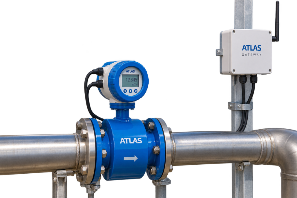
The stated accuracy of an electromagnetic flow meter does not compensate for poor installation. A partly filled tube, weak equipotential bonding, unsuitable liner or electrode materials, or incorrectly scaled outputs can compromise results in utilities and process plants. Reliable commissioning treats hydraulics, electrical bonding and automation as one system.
1. Faraday measurement and conductivity
A conductive liquid moving through the magnetic field induces a voltage related to its average velocity. The transmitter converts the measured signal into volumetric flow. This principle is not suitable for gases, steam or nonconductive fluids. The ATLAS-supplied TEM82E family currently lists a selection requirement above 5 µS/cm; verify the specific order code and actual liquid.
A full measuring section and appropriate electrode/liner contact are essential. Matching the nominal pipe diameter alone does not establish application suitability.
2. Full pipe, entrained air and straight runs
High points where air collects and arrangements with a free outlet can leave the sensor partly empty. Locate the flow meter where its measuring tube remains fully charged in normal operation; review venting and pipe geometry when needed. ISO 20456 emphasises full-pipe installation and following the manufacturer’s instructions.
Elbows, pumps, reducers and valves may disturb the flow profile. There is no universal upstream/downstream straight-run figure for every magmeter and installation; use the mounting diagram for the exact sensor and transmitter configuration.
3. Equipotential bonding and grounding rings
Inappropriate potential differences between the liquid, sensor and adjacent pipe can introduce unwanted noise. An uncoated metallic pipe and a plastic or internally lined pipe may need different bonding details. Grounding rings, electrodes and conductors must be selected from the specific manufacturer’s instructions and the plant electrical design.
Route signal wiring appropriately relative to drives and power conductors. Follow the cable-screen and sensor–transmitter wiring diagram rather than adding improvised ground jumpers, which can create unwanted loops.
4. Worked DN and analogue-scaling example
For a preliminary sizing calculation, Q (m³/h) = (π/4) × (D/1000)² × v × 3600. With an assumed actual bore of 100 mm and velocity of 1.4 m/s, flow is approximately 39.58 m³/h. This is not a guaranteed measuring range for every DN100 variant.
If a transmitter is configured for 4–20 mA = 0–100 m³/h, an illustrative input of 10 mA represents 37.5 m³/h: Q = (I−4)/16 × 100. Actual lower/upper range values, reverse flow and fault signalling must be checked before PLC commissioning.
5. Analogue, pulse, Modbus and external cellular telemetry
A 4–20 mA loop normally conveys a scaled process value; pulse outputs can provide volume increments; RS485/Modbus can expose flow and totaliser registers. Verify isolation, shielding, baud rate, parity, address, register type, byte order and engineering units on the actual delivered hardware.
ATLAS product information requires an appropriate external RTU or gateway for LoRaWAN, GSM/4G or NB-IoT telemetry; these are not default internal functions of the TEM82E sensor. ATLAS supports selection and supply of the flow meter family and evaluation of project-specific integration.
6. Commissioning and fault isolation
Document conductivity, liner/electrode compatibility, flow direction, pipe fill, potential bonding and required installation clearances. Verify zero-flow stability and compare the local display, field output, counter and SCADA values at meaningful operating points.
Do not hide an empty-pipe condition through a calibration adjustment. Submit DN, minimum/normal/maximum flow, fluid, pressure, temperature, supply, cable route, output and calibration-document needs when requesting a selection review.
Review the ATLAS electromagnetic flow meter range and submit your pipeline data for sensor selection and external telemetry assessment. ATLAS product information.
All numeric values are illustrative. Only the selected variant’s documentation determines approved performance and installation limits.