

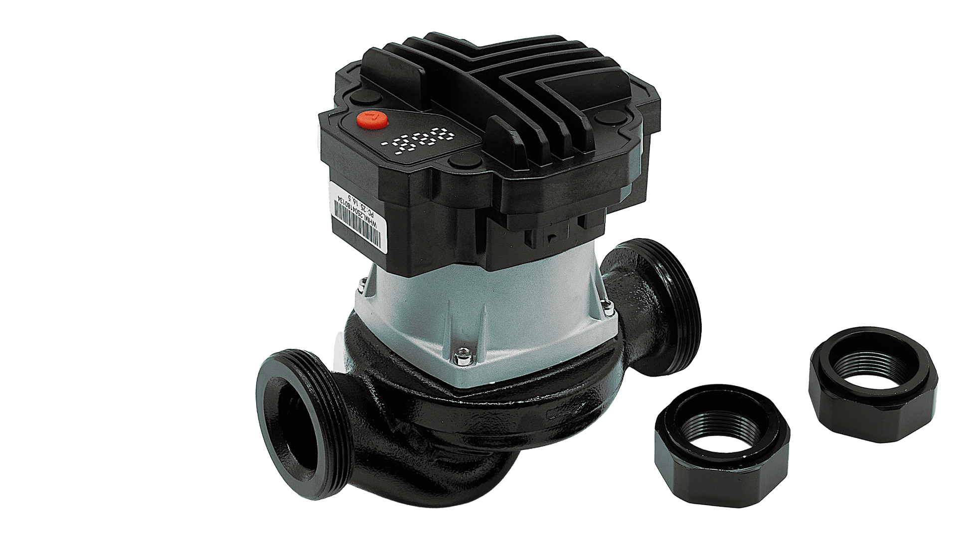
A circulation pump correctly selected for a Q–H duty point may still develop noise, vibration or inadequate flow under certain operating conditions. One possible cause is cavitation: vapour cavities form where local pressure falls below the liquid’s vapour pressure, then collapse as pressure recovers. This guide complements ATLAS’s existing pump-sizing and control-mode articles by focusing on absolute inlet pressure, temperature, site altitude and NPSH margin.
Air in the circuit is not the same as cavitation
Free air trapped after filling, dissolved gas coming out of solution and the formation of vapour cavities are separate phenomena. An air lock may prevent circulation; cavitation occurs when the liquid changes phase locally at low pressure and vapour bubbles implode downstream. Both can generate noise, but the diagnostic procedure is different. Installing an additional automatic air vent alone cannot correct insufficient NPSH.
Comparing available and required NPSH
NPSHA is the net positive suction head available from the installation, while NPSHR is associated with the selected pump and operating flow. If pressure is measured at the pump’s suction reference section and the local velocity-head term is neglected for preliminary assessment, NPSHA ≈ (pabs,inlet − pvapour)/(ρg). Pressure is in Pa, density in kg/m³ and the result in metres. Convert a gauge reading using pabs,inlet = patmospheric + pgauge. If pressure is measured upstream rather than at the actual suction connection, account separately for losses between the measurement point and the pump.
A practical design verifies that the installation offers the model’s required NPSH or specified minimum inlet pressure, plus an appropriate safety margin. Some small wet-rotor circulators publish minimum inlet pressure versus temperature rather than a full NPSHR curve; that product-specific instruction prevails over a generic calculation.
Worked comparison: why atmospheric pressure changes the result
For illustrative water at 80 °C, assume vapour pressure 47.4 kPa absolute and density 972 kg/m³. The suction gauge reads 0.0 bar(g). At an atmospheric pressure of 101.3 kPa, NPSHA ≈ (101.3−47.4)×1000/(972×9.81) = 5.65 m. If the local atmospheric pressure is instead a hypothetical 90.0 kPa, the same gauge reading gives 4.47 m. The second location has about 1.18 m less vapour-pressure margin even though its manometer looks identical.
Imagine, only for this example, that NPSHR at the operating flow is 4.0 m and a design allowance is 0.5 m. The first case meets 5.65 > 4.5 m; the second narrowly fails 4.47 < 4.5 m. None of these numbers is an ATLAS VFPUMP rating or a measured condition at a particular building.
| Assumed site condition | Atmospheric pressure | Suction gauge pressure | Approximate NPSHA |
|---|---|---|---|
| Higher atmospheric pressure | 101.3 kPa | 0.0 bar(g) | 5.65 m |
| Lower atmospheric pressure | 90.0 kPa | 0.0 bar(g) | 4.47 m |
Closed hydronic loops: static pressure is not pump head
In a full, closed heating loop, the circulating pump normally overcomes network friction rather than repeatedly lifting water to the building’s upper storeys. Static filling pressure, however, is essential to maintain sufficient absolute pressure at the pump inlet and positive pressure at high points. The expansion vessel connection, pump location relative to the point of no pressure change, dirty suction strainers and restrictions can alter local inlet pressure. A single remote boiler-room pressure gauge may not describe the suction connection during operation.
Water vapour pressure rises as temperature increases, reducing NPSH margin at the same absolute inlet pressure. Lower atmospheric pressure can add further risk. Never change system fill pressure without checking the expansion vessel, pressure safety devices, component pressure limits and the approved engineering design.
Seven checks when cavitation is suspected
Record pump speed and operating flow; determine whether the noise varies with load. Identify whether the instrument reads gauge or absolute pressure. Update liquid density and vapour pressure for actual temperature and glycol concentration. Inspect suction piping and strainers for excessive loss. Review expansion vessel and filling conditions against the design. Distinguish entrained air from vapour cavitation. Compare the actual inlet condition against the pump manufacturer’s minimum-pressure or NPSH requirement. Do not blindly throttle the circuit or raise its pressure without competent site review.
Applying this to ATLAS VFPUMP projects
ATLAS’s VFPUMP family must be assessed at the selected variant’s actual duty point and inlet condition. A general product description of control functions does not establish a guaranteed NPSHR curve, minimum inlet pressure or allowable temperature–pressure combination. Collect the exact model nameplate, current technical instructions and system schematic before accepting the installation.
Request engineering selection from ATLAS
Submit the required flow, supply/return temperatures, site elevation or atmospheric pressure, measured suction pressure, expansion-vessel configuration and pump model. Request a documented model-specific assessment. All numerical examples here are educational and not an ATLAS performance guarantee.
Technical references and verification date
Sources reviewed: 25 October 2026. Application requires the approved model-specific documentation.