
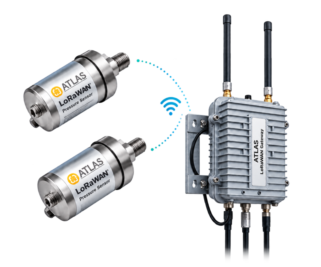
A flowmeter, pressure transmitter or process sensor can be accurate while its recorded data is wrong. Reliable instrumentation therefore needs correct signal scaling, electrical headroom, time-stamped logging and fault visibility. This engineering guide distinguishes analog current loops from RS485/Modbus RTU and turns both into a practical commissioning procedure.
Conceptual measurement and communications diagram, not an equipment wiring drawing. Scroll horizontally on narrow screens.
Separate measurement from communication
A 4–20 mA loop carries an analog representation of a process variable. RS485 is an electrical interface; Modbus RTU is a protocol that may run over it. An RS485 port is not proof of Modbus compatibility. Before design freeze, obtain wiring diagrams, transmitter power requirements, isolation arrangements and the actual device register map.
For an ATLAS/AtlasServer integration, define the approved field interface and software data model first. A feature planned for an R&D data logger must not be described as a verified capability of a shipping product.
Scaling current into engineering units
For a linear instrument, PV = LRV + [(I − 4 mA)/16 mA] × (URV − LRV). A 0–16 bar pressure transmitter therefore indicates 8 bar at 12 mA. If the receiver uses a 250 Ω shunt, its expected voltage is 1 V at 4 mA, 3 V at 12 mA and 5 V at 20 mA.
These figures are conditional on the actual transmitter configuration and input circuit. Input impedance, galvanic isolation, fault-current behavior and any digital linearisation must be confirmed against the relevant datasheets.
The 24 V loop-voltage budget
In a two-wire loop, the supply must cover transmitter operating voltage, receiver burden, cable drop and protection devices. Consider an illustrative 24 V supply and a transmitter requiring at least 10 V: the external circuit has at most 14 V to consume. At 20 mA, that is a theoretical resistance ceiling of 700 Ω before engineering margin is applied.
A receiver resistance of 250 Ω plus 100 Ω round-trip cable resistance causes a 7 V drop at 20 mA, leaving 17 V at the transmitter. Check the highest permitted supply voltage, transient protection and ambient-temperature effects too.
RS485 wiring, termination and bias
Use a twisted pair in a predominantly linear multi-drop trunk. Avoid uncontrolled star wiring and apply line termination at the two physical ends, not on every device. The official Modbus serial-line guidance illustrates 150 Ω termination and line polarisation; 120 Ω is also encountered in practice where cable impedance and equipment design warrant it. Select components using the project drawings and equipment manuals.
Manufacturers differ in their A/B and D0/D1 labels. Verify signal polarity at the terminals. Signal common, shield bonding and galvanic isolation belong in the site EMC design rather than a universal one-line rule.
Registers, units and timestamps
Match slave address, baud rate, parity and stop bits, then verify function codes and register offsets. Printed labels such as 40001 may not equal the zero-based address used by a software driver. For 32-bit floating-point or integer values, confirm byte/word order, sign and scale factor using a known reference value.
Keep the measurement timestamp distinct from the server receipt timestamp. A communication failure must not silently convert a missing sample into zero flow or zero pressure. Preserve quality flags, track device resets and validate the difference between cumulative totals and interval readings.
Nine commissioning checks
Record: (1) device identity and revision, (2) supply voltage, (3) receiver burden, (4) 4/12/20 mA accuracy, (5) physical termination, (6) serial-port settings, (7) register/word order, (8) cable-disconnect and reconnection behaviour, and (9) time sync and alarms. Bench injection validates the analog channel; live-site polling validates the actual cable and device network.
Close the FAT/SAT record with the meter certificate where relevant, tested firmware version, wiring plan, cable length, alarm screenshots and unresolved deviations.
Field acceptance checklist
- Confirm analog voltage/current versus RS485 interface.
- Document supply, burden and cable resistance.
- Verify RTU framing, register offsets and data types.
- Test timeout, CRC faults and reconnection.
- Reconcile engineering units and sample timestamps.
Technical questions
Does every RS485 device support Modbus RTU?
No. RS485 defines electrical signaling, not the application protocol. Obtain protocol and register documentation.
Does a zero reading prove a broken current loop?
Not by itself. Check input type, transmitter power, fault-current convention and logger scaling before diagnosing the wiring.
Scope and verification note: The 24 V, 250 Ω and transmitter voltage values are design examples, not verified specifications of an ATLAS device.