
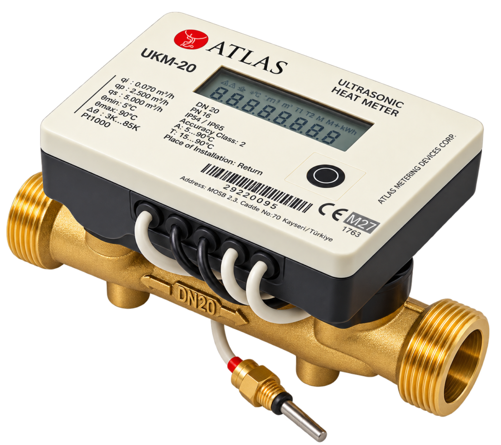
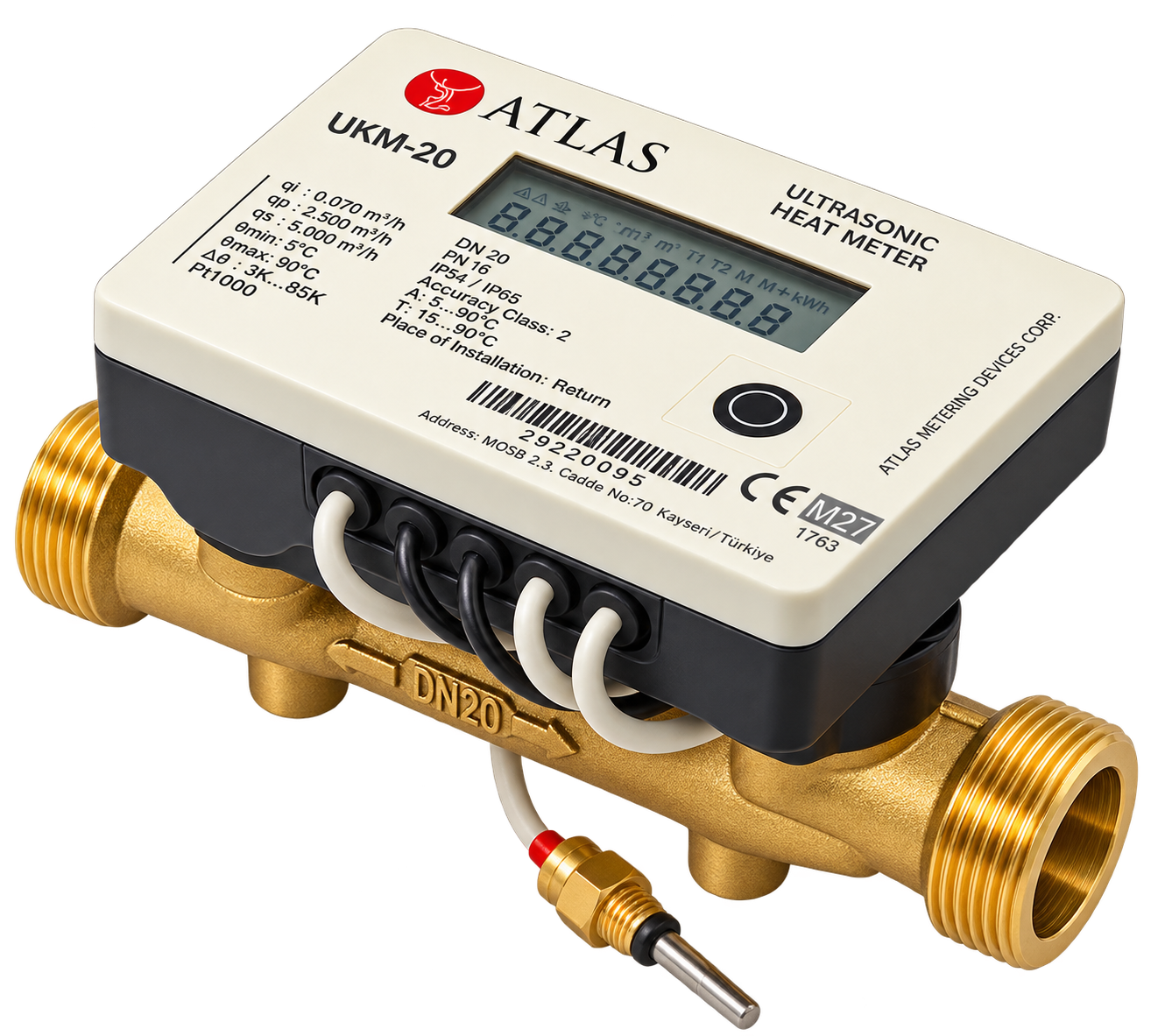
An accurately functioning flow sensor cannot compensate for an incorrectly measured difference between the supply and return temperatures. Thermal energy meters therefore treat their two temperature probes as a matched measurement pair, not as unrelated thermometers. This technical guide focuses on sensor matching, two- versus four-wire connection, lead resistance and installation acceptance. It does not duplicate the separate guides to heat-meter flow sizing or general low-ΔT operation.
Why differential temperature deserves its own error budget
For a heating circuit, the engineering relationship between transferred thermal power and flow is P ≈ ṁ·cp·ΔT. Certified heat meters use their approved calculator, temperature pair and metrological configuration to account for the relevant fluid properties. An individual probe reading that looks plausible does not prove that its difference from the second probe is correct.
Suppose the true supply is 55.0 °C and return is 50.0 °C, producing ΔT = 5.0 K. A systematic differential error of +0.10 K makes the indicated difference 5.10 K. Holding all other terms constant, the contribution of this error is approximately 0.10/5.00 = 2%. This is an illustrative sensitivity calculation, not a declared accuracy class or total error for any ATLAS product.
Pt100, Pt500 and what four-wire measurement changes
For platinum resistance thermometers of the IEC/EN 60751 family, ‘Pt500’ denotes a nominal resistance of 500 Ω at 0 °C. Near 50 °C, the local slope of the standard Pt500 resistance curve is approximately 1.93 Ω/K. Pt100 is more sensitive to a given extra series resistance when the error is expressed in degrees, because its resistance change per kelvin is smaller.
With a two-wire connection, the resistance of both conductors and their contact points adds to the element resistance. In a suitable four-wire system, separate current and potential leads allow the measuring electronics to suppress much of that series-resistance contribution. Four-wire connections are not automatically available in every meter, and the presence of platinum probes does not establish which Pt type an ATLAS variant uses. Verify the exact variant’s approved documentation.
Worked example: unequal lead resistance in a matched pair
Assume a two-wire Pt500 pair has a 0.20 Ω difference in the total series resistance between the hot and cold measurement paths. At approximately 50 °C, using dR/dT ≈ 1.925 Ω/K, the differential-temperature contribution is 0.20/1.925 ≈ 0.104 K. If true ΔT is 5 K, its magnitude is approximately 2.08% of the difference; at 20 K, approximately 0.52%. The sign depends on which lead pair has the larger extra resistance.
| Assumed true ΔT | Approximate differential error | Magnitude relative to ΔT |
|---|---|---|
| 5 K | 0.104 K | 2.08% |
| 10 K | 0.104 K | 1.04% |
| 20 K | 0.104 K | 0.52% |
This simplified calculation omits pair calibration, temperature distribution along the leads, compensation electronics and calculator algorithms. It must not be used as permission to alter an approved sensor assembly or a sealed measuring instrument.
What EN 1434-2:2022 says about leads and probe assemblies
EN 1434-2:2022 addresses temperature-probe construction, signal leads, two-/four-wire techniques and thermal response. For certain separable, paired resistance sensors using the two-wire method, the length and cross-sectional area of the signal leads must be equal. It also states that the lead length supplied by the manufacturer must not be changed. Some configurations call for the four-wire method. Consult the licensed current standard and the meter’s approved installation instructions for the applicable requirements; a general article cannot determine an individual product’s legal conformity.
A shallow insertion pocket, poor thermal contact, excessive response lag, reversed supply/return probes or an incorrect pocket location can cause errors independently of lead resistance. Matching cable length alone does not correct these installation defects.
Commissioning and service verification sequence
Check the meter label and approved configuration for probe type, pairing identification, serial numbers and calculator association. Confirm the supply and return positions from the project drawing. Check the specified pockets, insertion depths and sealing components. Document that leads have not been cut, spliced or routed improperly near interference sources, and that metrological seals remain intact. Where comparison is necessary, use a traceable test method under stable operating conditions. A casual thermometer check is not a substitute for a certified metrological test.
Applying the method to ATLAS heat meters
ATLAS offers UKM ultrasonic and mechanical thermal-energy meter families. Their temperature probe types, wiring arrangements, permissible lead lengths and approved matched pairs must be confirmed per model and option; do not transfer specifications from one family to another. Procurement and maintenance records should identify the meter model, paired probe assembly, lead length, pocket dimensions and sealing requirements.
Request an ATLAS engineering review
Provide the supply/return temperature range, minimum expected ΔT, temperature-pocket drawing and required meter model. Ask for a model-specific assessment using the latest approved technical file. This is an engineering explanation, not an instruction to break seals or modify a trade-approved instrument.
Technical references and verification date
Sources reviewed: 25 October 2026. Application requires the approved model-specific documentation.
- IEC 60751:2022 — platinum resistance thermometers · IEC
- EN 1434-2:2022 — thermal energy meters, construction · European national standards body / CEN
- EN 1434-2:2022 — clause 4.3 technical preview · CEN preview hosted by standards distributor
- ATLAS UKM heat meter family · ATLAS live catalogue
- ATLAS mechanical heat meter family · ATLAS live catalogue