
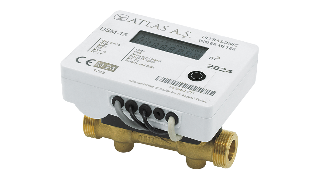
Ultrasonic water meters use electronic sensing, but they are not independent of hydraulic installation conditions. Maintaining a fully charged measuring section, preventing trapped air and following the model-specific upstream/downstream requirements all contribute to dependable measurement. This guide outlines practical checks for utilities, buildings and industrial water networks.
1. Why a fully charged pipe matters
OIML R 49 requirements address water meters installed in a closed conduit that is fully filled with water. Partial filling changes the liquid/air distribution and can take the instrument outside its intended measuring conditions.
Pay attention to high points where air can collect and to free-outlet arrangements that allow a line to drain. Select a position that remains water-filled in normal operation. Air-release equipment, non-return protection and draining arrangements must be considered in the hydraulic design.
2. Air bubbles and disturbed flow
Air pockets can influence ultrasonic signal quality and the flow profile. Avoid the blanket claim that all ultrasonic meters can always distinguish air without consequence. Use the selected model’s diagnostic indications and installation instructions.
Nearby elbows, pumps, valves or abrupt reducers may create disturbances. OIML R 49-1:2024 calls for sufficient straight lengths and/or flow straighteners, as specified by the manufacturer, where such disturbances affect measurement accuracy.
3. What does U0/D0 mean?
The U and D designations indicate upstream and downstream installation conditions. A claim such as U0/D0 is valid only for models and variants whose relevant approval documentation and installation instructions support it. It must not be assumed for every diameter or design in the same family.
Confirm mounting orientation, flow direction, straight-run length, DN, overall length and local pipework conditions against the actual supplied meter documentation. Weld projections, vibration and mechanical stress also deserve attention.
4. ATLAS USM20 flow-range example
The current ATLAS Ultrasonic Water Meters page lists DN20 USM20 with Q3 = 4.0 m³/h, Q1 = 0.010 m³/h, Q2 = 0.016 m³/h and R400. Q1 corresponds to 10 L/h; it does not promise accurate measurement of every possible drip. Compare the project’s minimum and maximum flow with the declared range.
Fill and vent the pipe gradually during commissioning. Verify tightness, flow direction and local indication, then compare it with the remote-reading values if installed. M-Bus, pulse or LoRaWAN connectivity depends on the specific ordered configuration.
5. Site acceptance questions
Is the measuring section always full? Is there a high point likely to trap air? Does the U/D layout satisfy the specific meter’s documentation? Are temperature, pressure and flow within range? Have water-hammer and mechanical loads been addressed? Are the serial number and communication identity recorded?
When readings look inconsistent, first investigate actual operating conditions, air removal and installation constraints before concluding that the instrument is defective.
ATLAS selection support
Send the DN, expected Qmin/Qmax, installation diagram and communication requirements for an ATLAS USM model-specific selection and installation review. Good measurement begins with correct placement.