
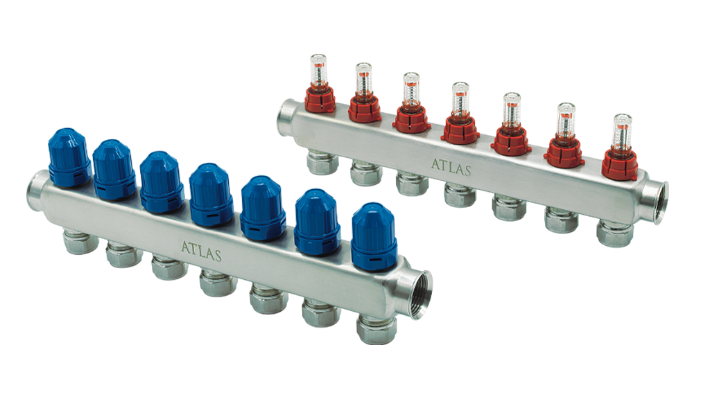
An underfloor heating system is not balanced merely because all manifold flowmeters display the same number. Each heating loop needs a design flow that reflects its room heat load, planned supply/return temperature difference and hydraulic resistance. A systematic approach also supports stable pump control and reliable room regulation.
1. Calculate water flow from heat demand
For water, the approximate relationship is P (kW) ≈ 1.163 × V̇ (m³/h) × ΔT (K). Therefore V̇ ≈ P / (1.163 × ΔT). This coefficient is approximate; glycol solutions require their own density and heat-capacity values.
Consider 80 m² with a calculated design heat loss of 60 W/m²: P = 4.8 kW. At a design ΔT of 5 K, total flow is about 0.825 m³/h, or 13.8 L/min. If six loops actually carry identical thermal loads, an initial target is roughly 2.3 L/min per loop.
These values describe a worked example, not an ATLAS manifold capacity claim. Different pipe lengths, room loads, pipe diameters and floor finishes require different loop-by-loop targets.
2. Why identical flowmeter settings may fail
A 600 W room circuit and a 1,000 W circuit have different water-flow needs at the same design ΔT. Long loops also tend to have higher pressure losses than short ones. Balancing means meeting the design distribution, not making the indicators look alike.
A flowmeter shows the current volume flow. Its reading can shift as zone actuators close, other loops open or the circulation pump changes operating mode. Set the initial flows under documented and repeatable commissioning conditions, preferably with the relevant zones open.
3. Commissioning sequence
Flush the circuits as specified by the project, fill and vent them individually, then complete leak and pressure tests. Label the loops and verify which room each serves. Confirm the pump operating mode and mixing-valve temperature setting before balancing.
Open the zones, set each loop to its calculated starting flow, allow the hydraulics to stabilise and record the total flow and supply/return temperatures. Test the room thermostat and actuator response afterwards.
Floor heating has significant thermal inertia. Do not judge room comfort a few minutes after adjustment; use flow, temperature trends and an adequate observation period.
4. The pump, mixing valve and actuators form one system
Pump selection must cover total design flow at the required head for the most demanding circuit. Excess differential pressure can cause noise and unstable control; insufficient head can starve remote loops.
A three-way mixing valve limits supply temperature, while thermal actuators control zones. Neither replaces correct hydraulic design. ATLAS manifolds, mixing components and circulators should be specified against the same hydraulic schematic.
5. Five avoidable mistakes
Using one default L/min value for all loops; balancing before venting; reading meters with closed actuators; ignoring the flowmeter measuring range; and failing to recheck balancing after changing the pump mode. The initial preset still needs verification in operation.
Where ATLAS fits
Bring the room heat-load schedule, pipe lengths, design ΔT and pump duty point to the product-selection process. See the ATLAS Underfloor Heating Systems range for manifolds, actuators and related hydronic equipment.