
1. Pre-Installation Technical Compliance and Preparation
- Characteristic Compliance: The pressure class (PN) and maximum fluid temperature of the device must be suitable for the installation. Pressure loss calculations must be compatible with the pump selection.
- Pipe Diameter and Reduction: If the installation pipe is wider than the meter, an appropriate reducer must be used.
- Installation Cleaning (Critical): Before installation on existing plumbing, the line must be flushed, and all sediment and particles must be removed.
- Use of Blind Plug: In models with measuring capsules, a plastic blind plug should be installed instead of the meter during the construction and flushing phases; the meter unit (head) should only be installed right before the acceptance phase.
2. Hydraulic Installation Rules
- Strainer: A strainer must absolutely be used just before the meter in the direction of the flow. Additionally, a dirt separator (spirovent) is recommended on the boiler room return line.
- Valve Placement: For ease of service, isolation valves matching the pipe diameter should be placed before and after the meter.
- Straight Pipe Distance: For accurate measurement, an empty straight pipe length of DN10 before the meter and DN8 after the meter must be left.
- Installation Direction: The arrow mark on the meter body must point in the same direction as the water flow. In case of reverse installation, the device will not measure.
3. Installation of Temperature Sensors
- Line Separation: The return line sensor must be installed on the “cold line,” and the supply line sensor must be installed on the “hot line.”
- Positioning: The sensor must be immersed to at least half of the pipe diameter but must not touch the inner surface of the sleeve.
- Cable Protection: Sensor cables must never be cut, shortened, or spliced.
4. Environmental Conditions and Protection
- Physical Protection: The device must be kept away from shocks, vibrations, excessive stress, and places with water dripping/leaking.
- Air and Cavitation: Unfavorable hydraulic conditions such as air in the plumbing and cavitation must be prevented.
- Chemical Use: If an anti-corrosion chemical is to be used in the plumbing, a guarantee must be obtained that it will not damage the device.
5. Calorimeter Installation Diagram and Considerations
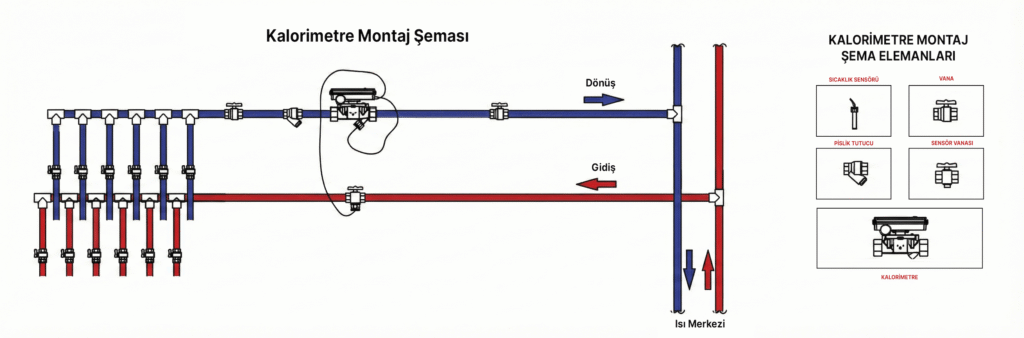
The installation of the calorimeter must strictly be carried out by experienced professionals. It should be installed on the water return line (manifold) leaving the apartment, not the supply line (hot water inlet) entering the apartment. The arrow direction on the meter must also face the riser line.
What Happens if the Calorimeter is Installed Backwards?
If the calorimeter is installed backwards, it cannot measure. The installation must be corrected according to the installation diagram as soon as possible.
6. Commissioning and Screen Usage
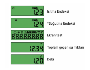
- The calculator unit has an 8-digit LCD screen with special characters. All information menus can be accessed using the reading button located below the digital screen.
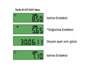
- There are 2 information menus: Screen 1 / Main Menu and Screen 2 / Statistics Menu.
- When the button on the digital screen is not pressed, the standard display in the ‘Main Menu’, which is the ‘Total Heat Energy’ value, is continuously shown.
- Pressing the button once is sufficient to read the values in each information menu.
- To view the next information menu, it is necessary to press and hold the button for 4 seconds.
- Press the button in quick succession to sequentially view the information in your current menu.
- If the screen is not used for 1 minute, it will automatically return to displaying the ‘Total Heat Energy’ value in the Main Menu.